

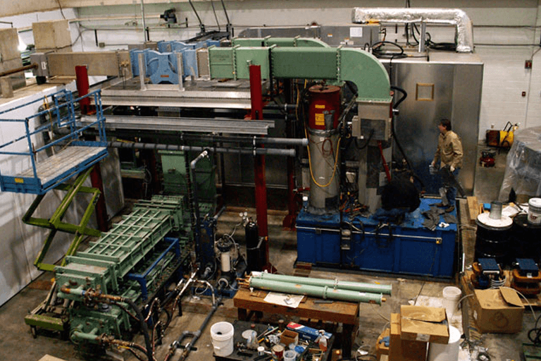
This page documents the history of the systems and instrumentation installed at the Low Energy Neutron Source (LENS) at the Center for Exploration of Energy and Matter (CEEM) at Indiana University. The following accordion features this documentation broken up into each year from 2004 through 2014.
LENS History
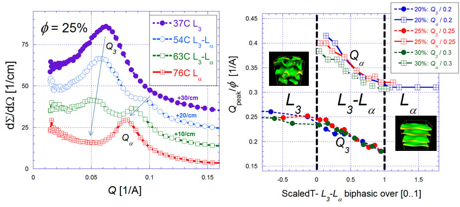
AOT membrane phase miscibility gap - April 2014
The LENS SANS instrument has recently been used to track the behavior of coexisting membrane phases of the surfactant AOT in heavy brine.
The figure at left shows scattering curves as a 25% volume fraction AOT sample was heated: a low Q peak indicative of the convoluted L3 sponge phase disappearing while a higher Q peak indicative of an Lα lamellar phase appears. The figure at right shows, for several concentrations, how these coexisting phase peak positions move together at a roughly constant ratio (~1.7) which is rather higher than the bulk single phase peak ratio (~1.25). These trends reflect the equality of Gibbs free energy of the phases as a positive membrane curvature modulus favoring the L3 becomes smaller while more thermal energy can be taken up by extra bending modes in Lα, balanced against the entropy difference between the phase topologies.
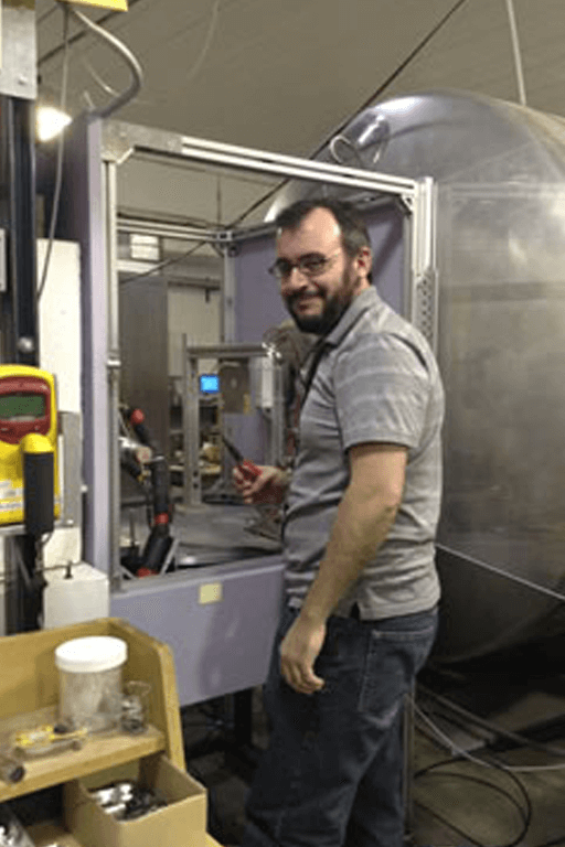
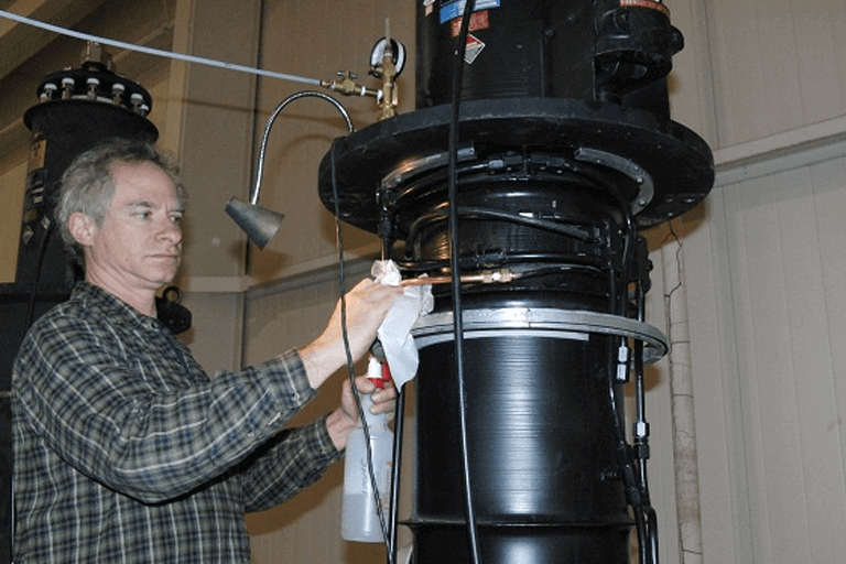
D2O scattering cross-section measurements at LENS - July 2014
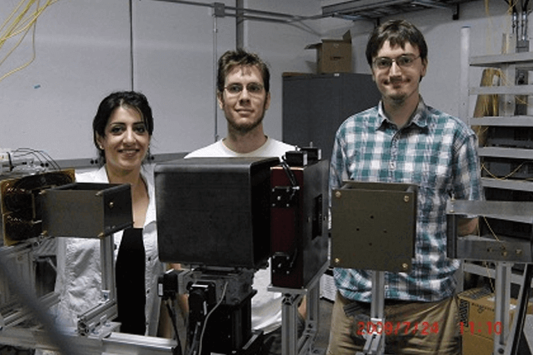
The LENS SANS instrument has recently been used in collaboration with colleagues from the CNEA, Bariloche Argentina. Shown here is Dr Ignacio Marquez Damian preparing the setup for measurements. The measurements were performed to test predictions of current scattering models as a function of temperature.
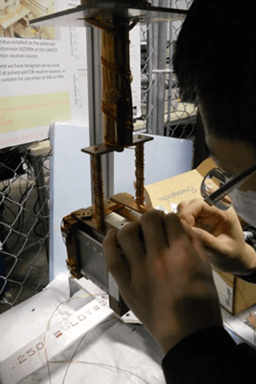
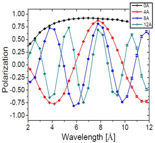
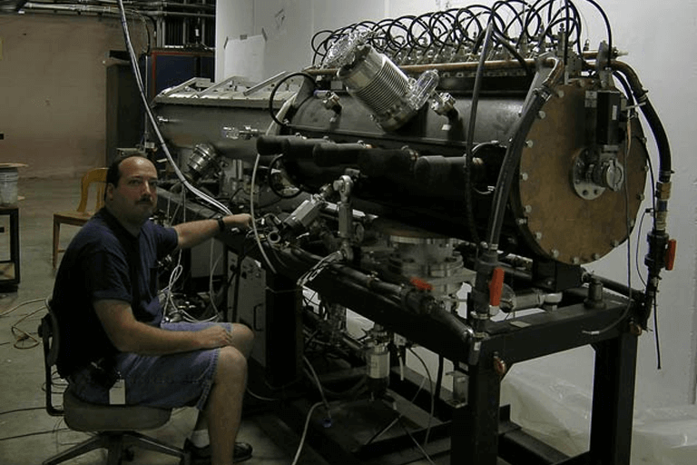
January 2013 – Spin precession device – Cryocup tested on Spin Echo Scattering Angle Measurement (SESAME)
First tests of spin manipulation device performed on the SESAME beamline. Left - Neutron polarization as a function of wavelength for a single precession device with various currents, using a 15×15mm2 beam, lines are guide to the eye. Right – LENS student T.Wang assembling the device he built prior to testing.
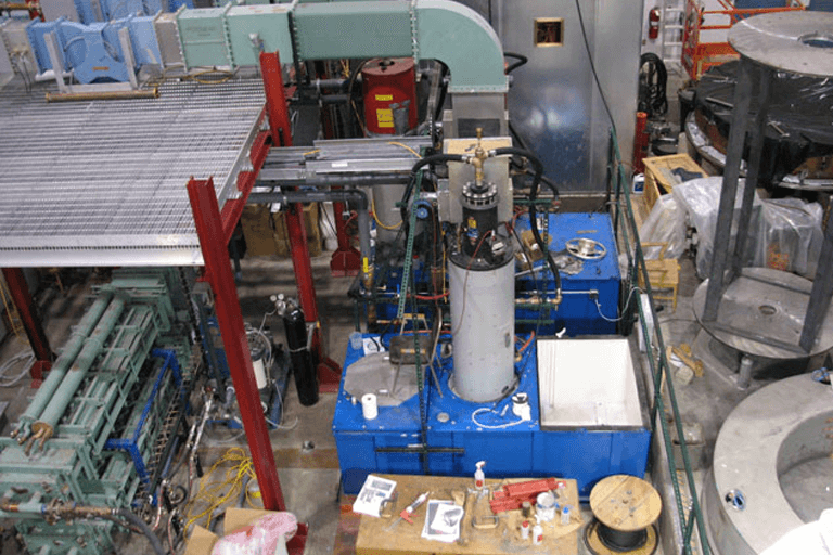
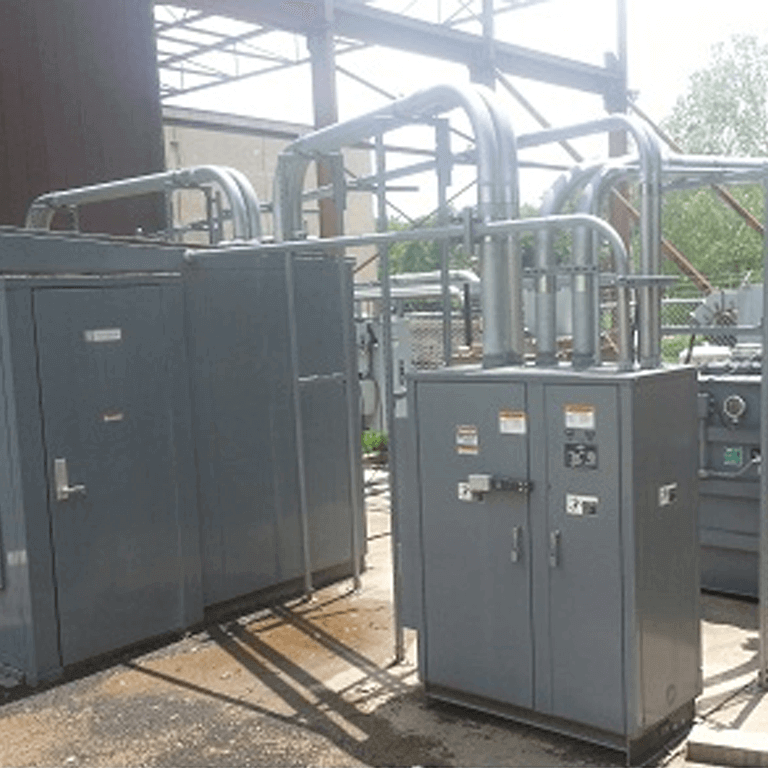
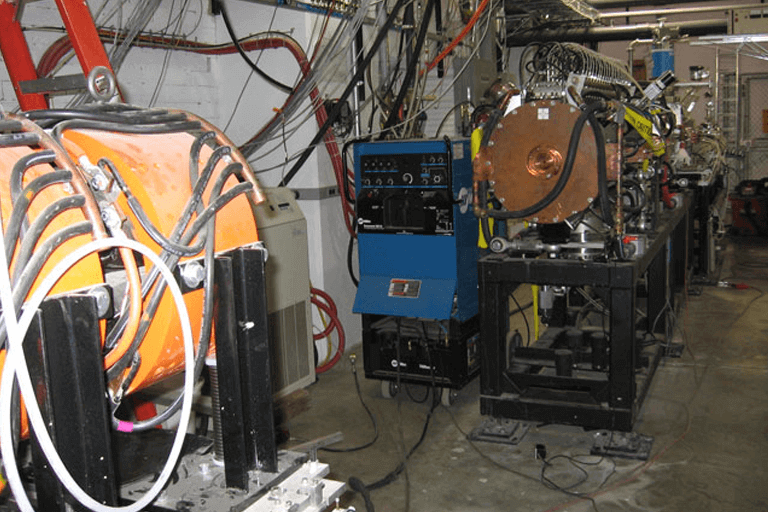
February 2013 –Installation of continuously pumped 3He analyser
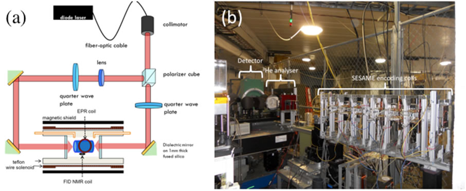
The installation on the LENS instrument SESAME of a continuously pumped 3He analyzer was completed. The device maintains a 3He polarization of 73% during experiments. This device will be used to provide polarization analysis for experiments using SESAME including SESANS and test of various spin manipulation devices.
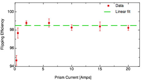
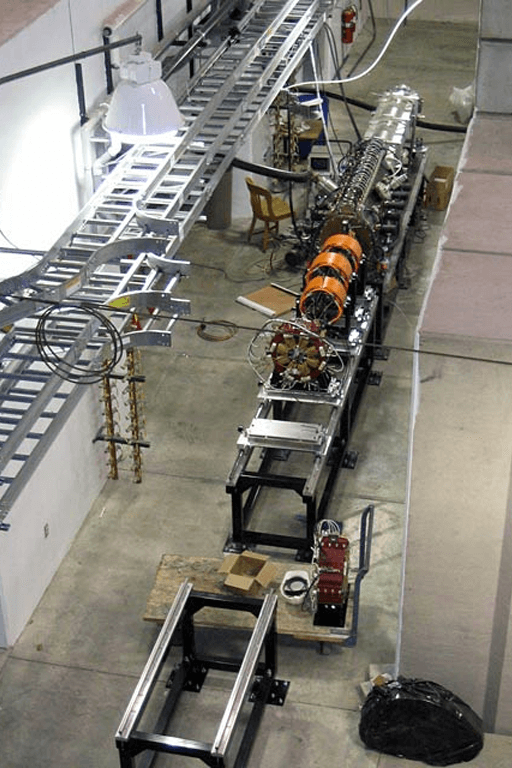
November/December 2013 -Testing of new superconducting Wollaston Prism at LENS and NIST
The LENS instrument SESAME was used to test a superconducting version of a neutron Wollaston prism (top left) showing the flipping efficiency is independent of current, except at very small currents. The device was further tested at the MAGIK instrument at NIST (bottom left). These measurements showed a well defined flipping plane with very low polarisation losses (bottom right). The details of these experiments are in F.Li et al. Rev. Sci. Inst., 85, 053303(2014).
February 2012
New NREF DUT holder is installed in TMR1.
June 2012
Successful test of pelletized moderator.
June 2012
NBL2 Moderator Imaging Station (MIS) is installed and takes first beam.
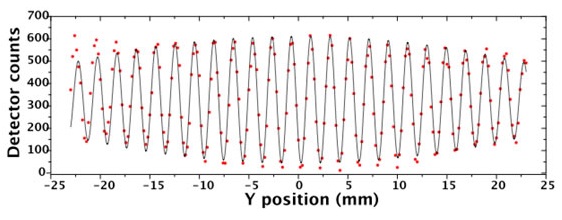
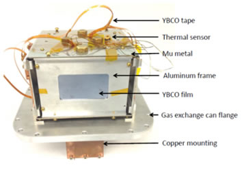
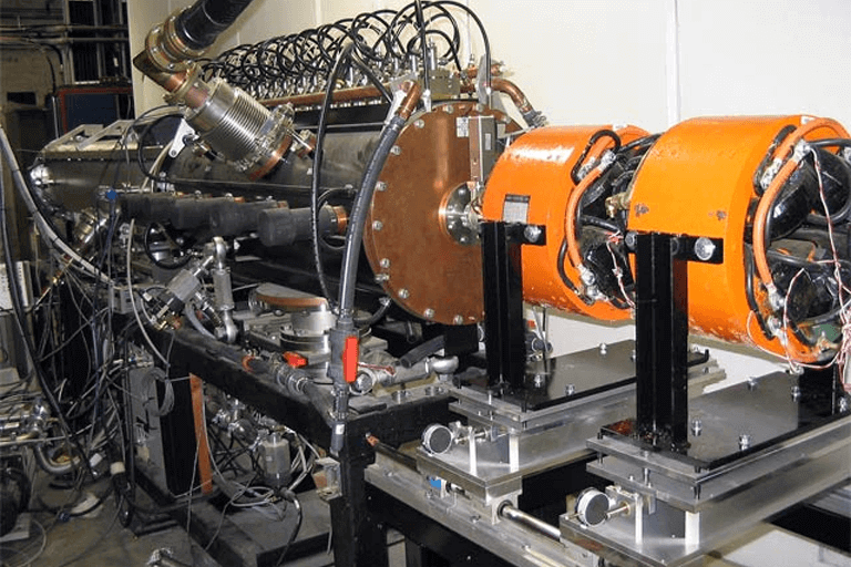
October 2012 – YBCO base Cryoflipper tested on SESAME
Our first device in our spin manipulation project a cryoflipper using a single film of YBCO was tested on the SESAME instrument (left). A high and wavelength independent flipping efficiency was found for the device (right).
May 2011
Klystron tube base develops a water leak inside the oil tank. the leak was fixed in place but required 2 weeks to recover the oil voltage holding capabilities.
April 2011
First commercial customers for NREF.
April 2011
New emission time apparatus commissioned for Moderator studies.
June 2011
New target design runs for 75 kW-days of beam on target (a new record). Failure mode was O-ring radiation damage.
July 2011
Klystron beam switch tube assembly upgraded to version 2. The second klystron tank was upgraded to the new switch tube in August.
January 2010
Klystron beam switch tube new assembly version one installed.
April 2010
New Target design installed. This design has the beryllium target normal to the proton beam and a thickness of 1.2 mm so that the protons are stopped in the cooling water and not in the beryllium.
July 2010
Target failure water impurities build up on the target back side.
October 2010
Target water cooling system upgraded with DI filters.
October 2010
SANS frame overlap chopper installed.
January 2009
Klystron tube water line repair by Jack Doskow.
April 2009
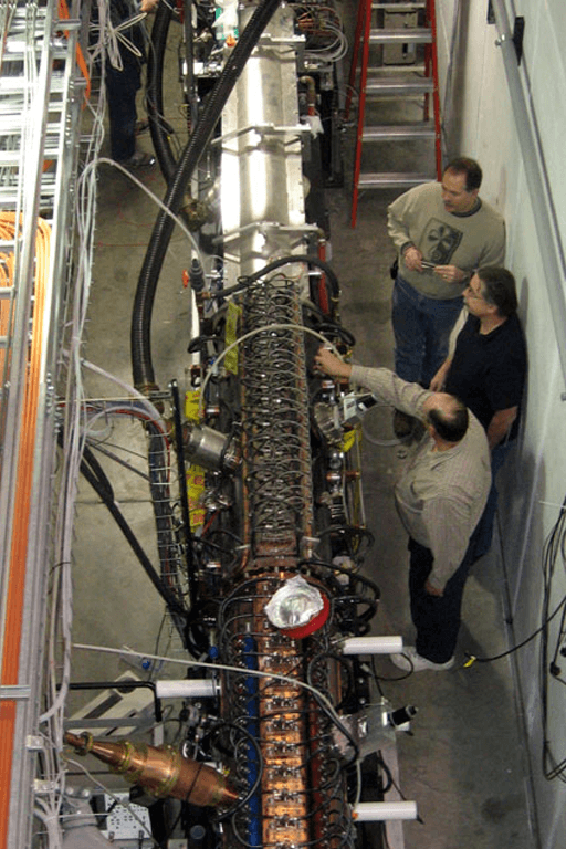
SESAME 3 degree neutron bender/polarizer installed.
April 2009
SESAME Primary flight path complete including mirrored guides and shielding. First version of triangle coils being installed.
May 2009
Klystron deck failures being debugged.
May 2009
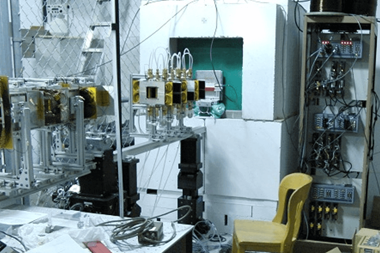
SANS Detector electronics being debugged.
May 2009
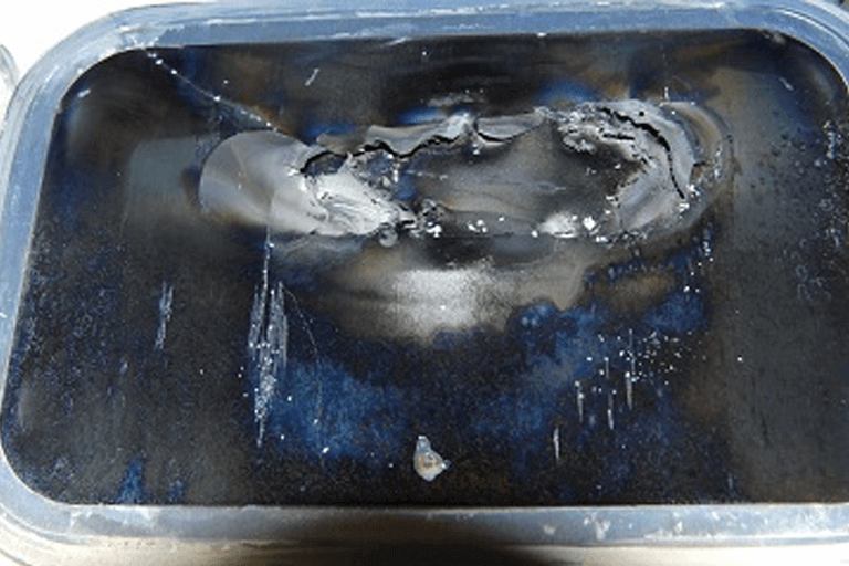
Target failure blisters!
June 2009
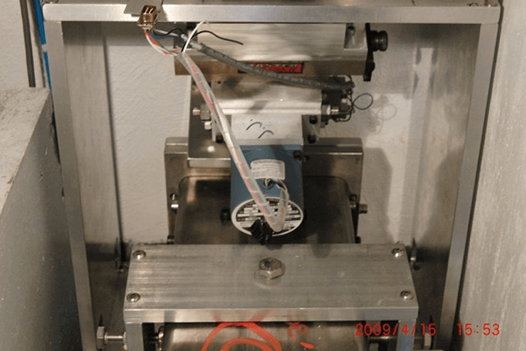
SANS sample exchanger installed.
July 2009
Target failure focusing.
July 2009
Target failure blisters!
July 2009
SESAME first beam.
August 2009
Klystron beam switch tube dies forcing 7 MeV operations throughout the rest of 2009.
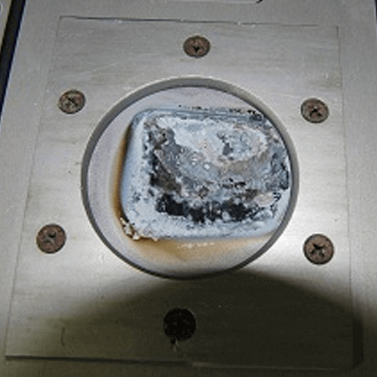
December 2009
Target failure 7 MeV, blisters on blisters.
January 2008
Second high-voltage tank prepared for the installation of the third klystron which is needed to deliver power to the second DTL section to deliver 13 MeV protons.
January 2008
6 MeV DTL section installed in the LENS proton Beam Line. Beam (at 7MeV) was first successfully passed through this section of the accelerator on 24 January, 2007. Energizing this section of the accelerator (to reach 13MeV) awaits completion of the installation of a third klystron.
February 2008
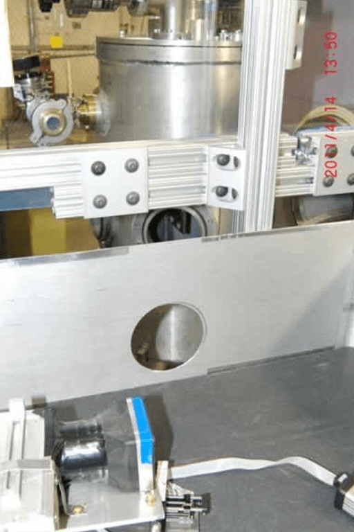
Final section of the primary flight path and the sample enclosure for the SANS instrument.
March 2008
Klystron #3 being installed with Bill Reass from LANL.
April 2008
Klystron #3 supplies power to DTL #2 giving 13 MeV protons for the first time to the beryllium target.
July 2008
Target collimator and other beam diagnostics installed.
September 2008
LENS operating from the new klystron high voltage power supply attaining 2 kilowatts on target.
November 2008
Target Failure from target cooling system contaminants.
December 2008
Klystron Capacitor bank upgrade complete. This allows longer klystron pulse width with lower voltage sag.
December 2008
0.9 millisecond proton pulse width (6 kilowatts beam power) demonstrated.
January 2007
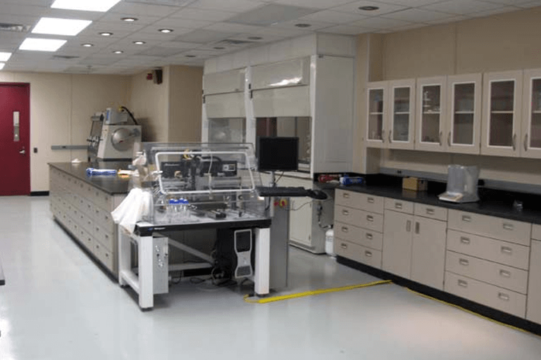
The Chemistry lab includes generous counter space, and standard instrument such as balances, pH meters, glassware etc.
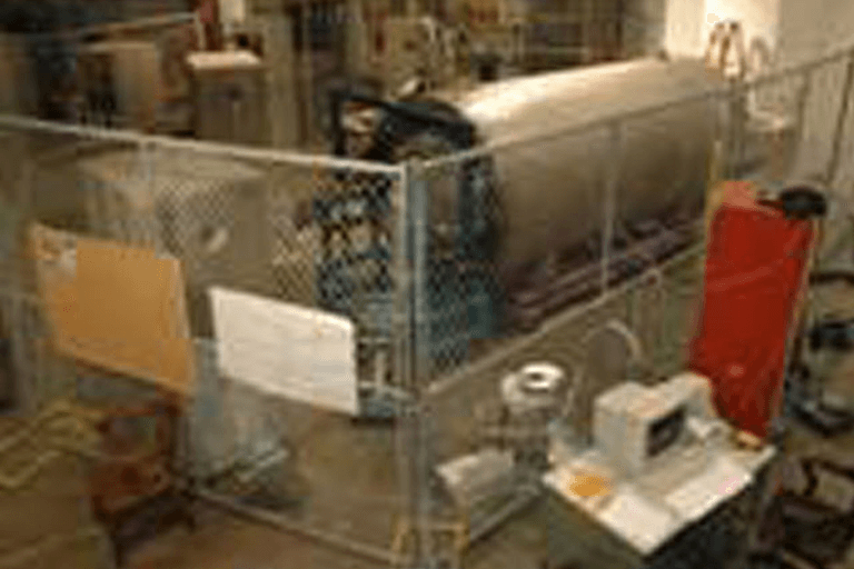
February 2007
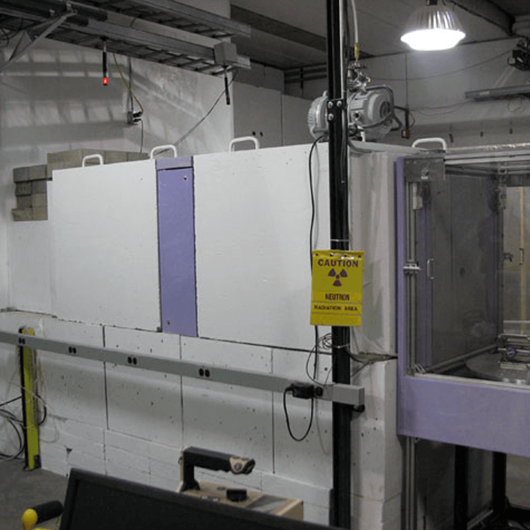
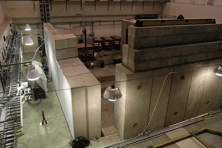
Reconfiguration of the first TMR vault for radiation effects research. Decommissioning of the prototype SANS and radiography instruments. The tape on the floor shows the future location of the main wall of the second TMR vault.
April 2007
The vault will be finished with standard wall blocks, but this section is pour to eliminate any seams near the four penetrations for neutron instruments.
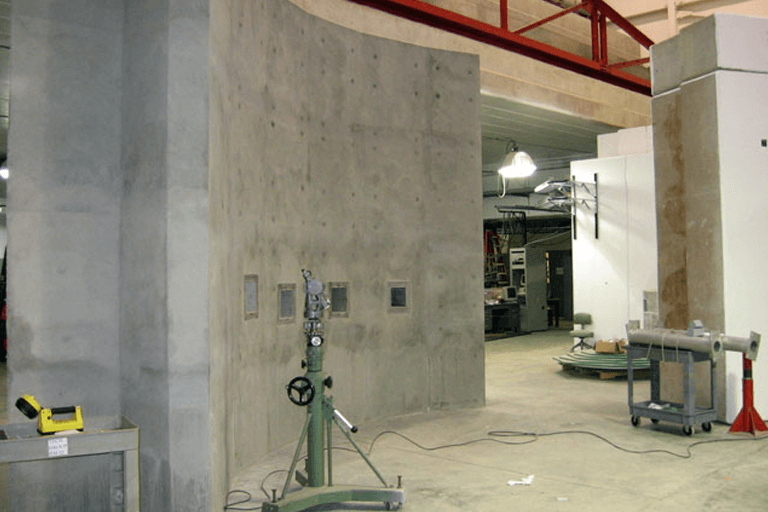
April 2007
Completion of the main wall for the second TMR vault. Penetrations for the four instrument beam lines are visible.
October 2010
Installed DUT holder (version 1) for neutron radiation effect users.
May 2007
Installation of the second TMR within the new vault. Shielding is also in place around the SANS beam line, and wall penetrations for two future instruments are visible on the left.
December 2007
Four shutters installed in the new TMR vault. Shielding between the beam lines is not yet completely installed. The first two sections of the evacuated SANS beamline are visible (one on top of the (closed) shutter).
December 2007
Original accelerator was moved back approximately 2.5 m in preparation for the installation of the second Drift Tube Linac (DTL). This second DTL will raise the proton beam energy from 7 MeV to 13 MeV, thereby increasing the neutron flux per unit proton current by a factor of roughly 4.
March 2006
First Emission time distribution measurement from the LENS moderator. MCNP simulation of the emission time distribution is shown as the blue line, the data points (for a 150 μsec proton pulse width) are shown in black. The long-time decay constant is set by the absorption characteristics of the LENS water reflector.
December 2006
Klystron RF power systems connected to the LENS accelerator for the first time. This is the first step in a major power upgrade that will take approximately 18 months to complete. It allowed peak currents up to 25mA (increased from 10mA), beam powers up to 1 kW (up from 150 W), and pulse rise-times as short a two microseconds.
December 2006
First klystron-powered proton beam delivered to a fluorescent screen.
March 2005
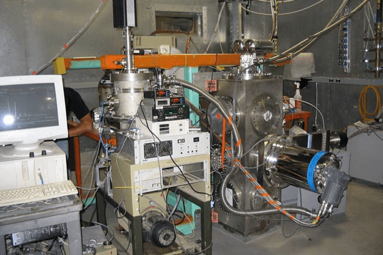
Initial instrument setup at LENS. SANS installed in the foreground. This instrument is prototypes designed more for studying the source and commissioning detectors than for investigating materials due to the very low beam power (150W).
April 2005
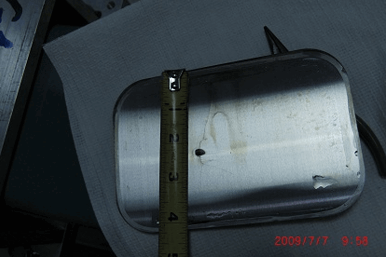
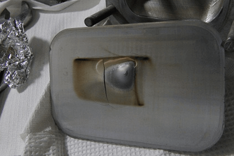
Cryogenic moderator inserted into the Target Moderator Reflector Assembly.
April 2005
First cold neutron spectrum recorded from the LENS moderator. The simulation is from an MCNP calculation with the smeth22 kernel.
August 2005
First studies of neutron radiation effects in electronic circuits.
February 2004
View of the LENS accelerator area looking south from the old cooler vault roofbeams. The cooler injector synchrotron (CIS), partially obscured by the roofbeams, is still assembled and in place.
April 2004
Same view as above with the roof beams above the old cooler injector synchrotron (CIS) removed. The entire CIS is removed as well.
May 2004
Same view as above with a new shielding wall between the proton accelerator and klystron gallery. (neither are in place yet). The accelerator will be placed to the left of this wall, and the klystrons will be located to the right.
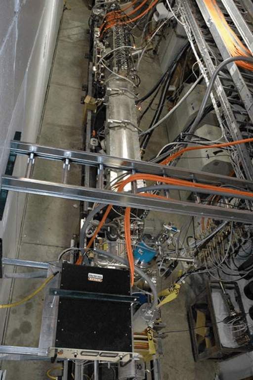
Part of the LENS SANS (Small Angle Neutron Scattering) tank, donated by the University of Missouri, can be seen in the foreground.
June 2004
The PL-7, originally the injector for the CIS synchrotron ring, is moved into place. The PL-7 proton accelerator consists of two accelerating stages - a 3-MeV RFQ (radio frequency quadrupole) and a 4-MeV DTL (drift tube linac).
August 2004
The injector for the LENS proton accelerator in the development area. Pictured from left to right (in the larger image) are Andy Sebold, Bob Brown, and Ron Kupper.
August 2004
The PL-7 viewed from the roof beams of the old cooler vault, looking south.
August 2004
Dave Townsend connecting coolant lines to the Linac.
September 2004
Installation of the proton beamline begins. The orange components are quadrupole magnets used to focus the proton beam as it leaves the accelerator.
September 2004
Close-up of the end of the PL-7 proton accelerator showing two of the quadrupole magnets. The RF power is now attached to the DTL.
September 2004
Installation of the proton beamline continues. The yellow magnets are refurbished quadrupoles from the Cooler synchrotron.
September 2004
The LENS cryogenic moderator system under development in the LENS staging area.
September 2004
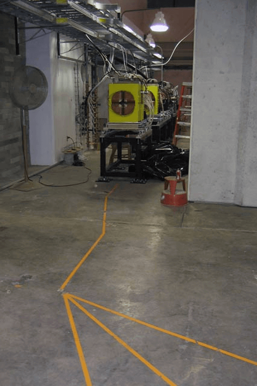
The LENS beamlines are surveyed in and their paths are marked on the floor with orange tape. The three paths in the foreground are the three LENS neutron flight paths. The point that they emanate from is where the moderator is located.
October 2004
The concrete pier that will support the LENS TMR (target/moderator/reflector) assembly is poured. In the foreground the radiation shielding around the TMR vault is taking shape.
October 2004
A view of the TMR vault. The finished pier for the TMR is shown on the left, and the support for the proton beamline is shown on the right. The door in the back leads through the maze to the LENS accelerator control area.
October 2004
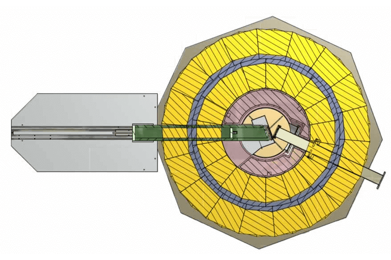
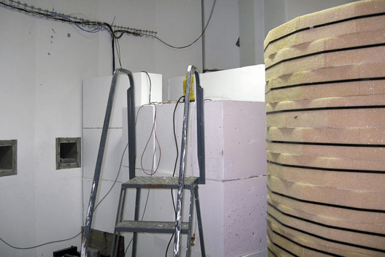
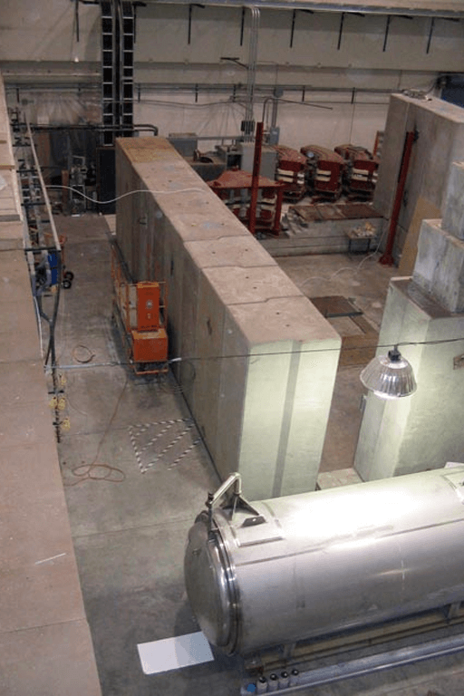
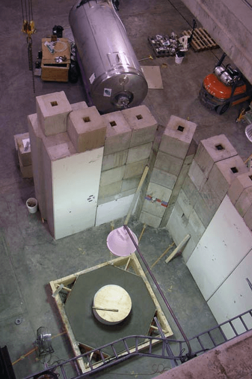
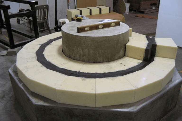
Stacking of the TMR shielding commences. The TMR shielding consists of about 500 tightly-fitting blocks made from layers of lead and boron-impregnated polyethylene. The lead and boron reduce the flux of neutrons and gamma rays that are emitted from the TMR assembly.
November 2004
The final elements of the proton beamline are positioned. The blue components are dipole magnets used to steer the proton beam correctly onto the LENS neutron production target.
November 2004
Assembly of the TMR shielding continues. Almost all of the proton beamline magnets are installed and aligned.
December 2004
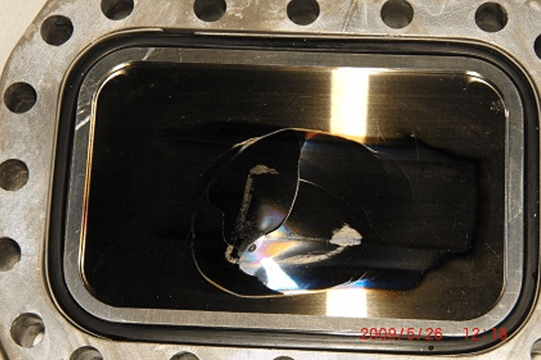
The final portion of the proton beamline and the reflector are installed. The beryllium neutron-production target is positioned within the reflector vessel. The reflector is filled with water are serves the purpose of “reflecting” stray neutrons back into the moderator. The moderator system is inserted into the rectangular cavity at the top of the reflector vessel. The shielding wall, half-stacked in the background, is to provide radiation isolation between the TMR vault and the proton accelerator vault.
December 2004
The completed accelerator system including the new ion source, foreground.
December 2004
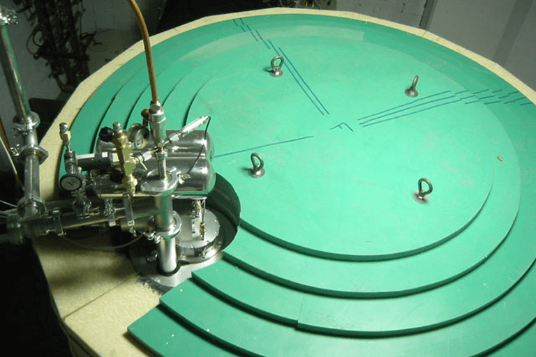
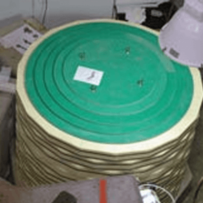
The completed TMR assembly. The green circular layers on top are sheets of borated polyethylene. The PVC pipe on the left is the temporary neutron flight path leading to the SANS instrument.
December 2004
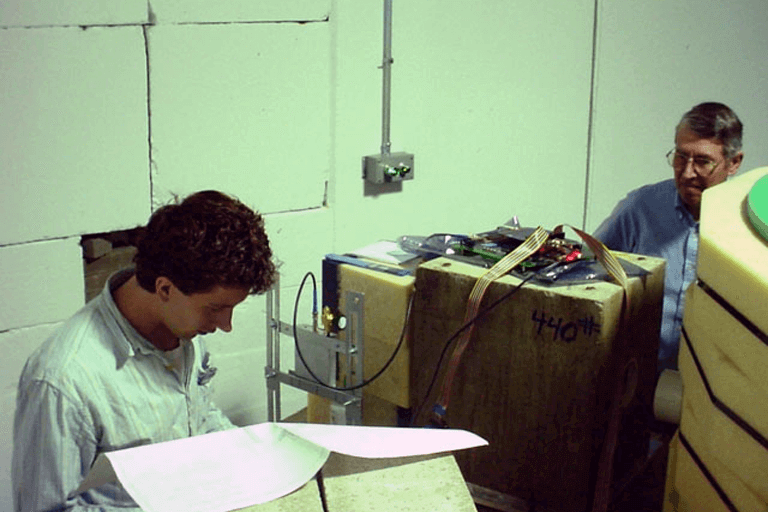
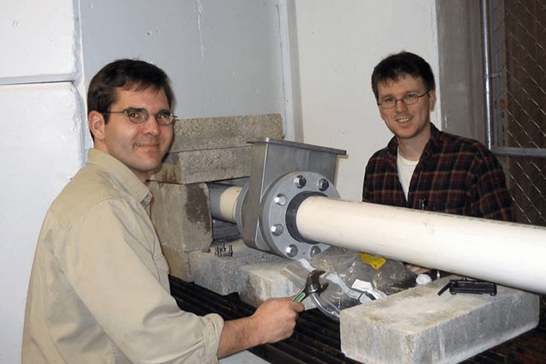
LENS graduate students Nick Remmes and Chris Lavelle make final adjustments to detectors on the SANS neutron flight path in preparation for the first neutron beam.
December 2004
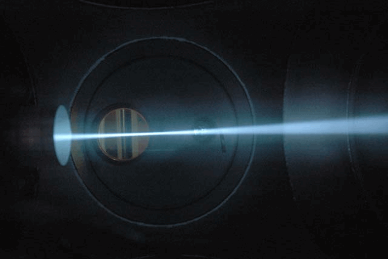
40 mA of 25 keV protons passing through a vacuum chamber with an Argon background gas at a pressure of about 5 * 10**-5 Torr.